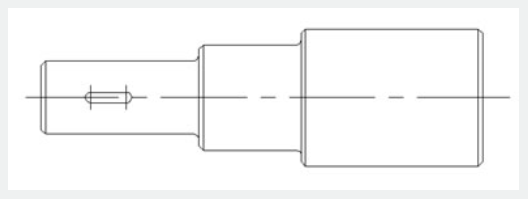
Actually, limited to the demand of the material mechanics characteristics, keyway is only allowed to be placed on the central line. So, a horizontal movement is enough for keyway and the movement to other direction is not meaningful. Next we will take advantage of the linear parameter to define the keyway's movement direction on the central line of the step shaft.
1.Draw
Draw the drawings as in the following picture and define it as a block.

2.Add linear parameter
The way of adding a linear parameter is similar to dimension, both try to put the absorption point of the parameter on the central line of the step shaft.
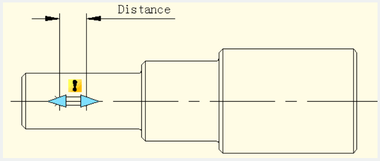
3. Add Move Action
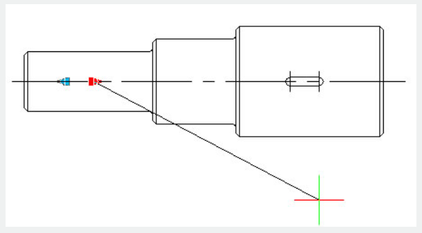
Different from the point move, after specifying the parameter, the system will prompt: Specify parameter that is related to movement. Select right grip of parameter as "Related parameter point", as shown in the following picture.
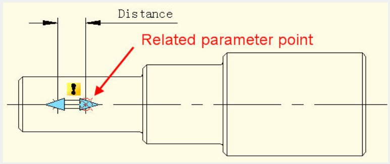
The parameter point we mentioned corresponds to the operate point of Move. After exiting Block Editor you can drag this point to make dynamic block change correspondingly.
After selecting the related parameter point you can specify the move objects for action, as shown in the following picture.
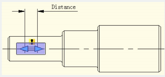
Place action label, save and exit dynamic block.
4.Testing Dynamic Block
Select dynamic block and drag the right grip of the parameter. Meanwhile, no matter how the cursor moves, the keyway is limited to the central line of the step shaft. That is to say with the limitation of the linear parameter, the dynamic block can only move along the direction specified by the linear parameter.
Article ID: 2527
Created: November 9, 2021
Last Updated: November 9, 2021
Author: GstarCAD MY /KW
Online URL: https://www.kb2.gstarcad.com.my/article.php?id=2527