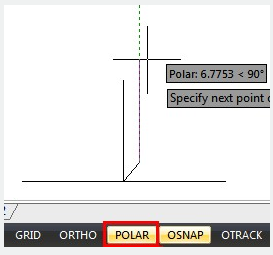
Polar tracking is used to display temporary alignment paths defined by the polar angles you specify, while you are creating or modifying objects. You can set the angle base (ANGBASE)direction in the Drawing Units dialog box.
Alignment paths and tooltips will be displayed when you move the cursor near the polar angles. To draw your object, you can use the alignment path and tooltip. To find, where a polar alignment path intersects another object, polar tracking with Intersection and Apparent Intersection object snaps can be used.
Specify Polar Angles
The polar angle (POLARANG)increments can be set to 90, 60, 45, 30, 22.5, 18, 15, 10 and 5 degrees or other angles which you specify in the Polar Tracking tab of Drafting Settings dialog box.

The orientation of 0 depends on the angle you set in the Drawing Units dialog box (UNITS). The direction of snap (clockwise or counterclockwise) depends on the units direction you specify when setting units of measurement.
Above video sources from TUTORIAL - GETTING STARTED WITH GSTARCAD, enrol now for free.
Article ID: 2495
Created: November 9, 2021
Last Updated: April 14, 2022
Author: GstarCAD MY /KW
Online URL: https://www.kb2.gstarcad.com.my/article.php?id=2495