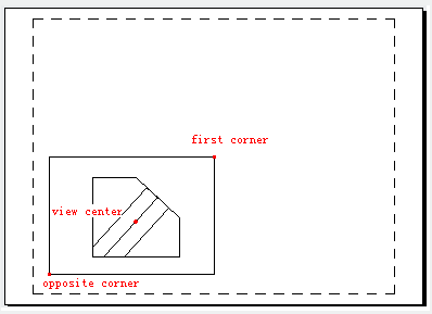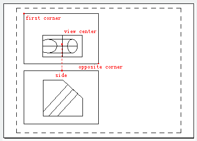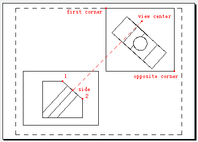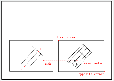
The SOLVIEW command is used to create orthogonal views, layers and layout viewports for 3D solids.
Command Access:
Menu : Draw> Modeling> Setup>View
Command: SOLVIEW
Command Prompts:
Enter an option [Ucs(U)/Ortho(O)/Auxiliary(A)/Section(S)]:
Function Description:
Note: the SOLVIEW command must run in the layout tab, if running it in the model tab, the last active layout tab will become current layout tab.
Relative Glossary:
The SOLVIEW command will place objects on "VPORTS" layer, if it does not exist, the SOLVIEW command will create it.
The final drawing view will be generated by all information saved in its viewport.
The SOLVIEW command creates layers to place visible lines and hidden lines for views created by the SOLDRAW command (view name-VIS, view name-HID and view name-HAT), as well create layers to place visible dimensions for each viewport (view name-DIM).
Warning : when running the SOLDRAW command, it will remove and update saved layer information. Please do not place information on those layers permanent.
UCS:
Create projection viewport according to UCS. If there is no viewport existing, the "UCS" option is a good way to create original viewport, and other viewport could also be created through this way. All options of the SOLVIEW command should be operated in existing viewport.
Users could use current UCS or previously saved one as the projection plane. The created projection viewport is parallel to XY plane, the positive direction of X axis is along right direction and the Y axis is along vertical direction.

Named:
Create a profile view by the XY plane of named UCS.
Input the UCS name and view scale. Users could scale viewport by inputting view scale in the paper space. The view center is determined by scope of current model space.
World:
Create a profile view by the XY plane of WCS.
Input the UCS name and view scale. Users could scale viewport by inputting view scale in the paper space. The view center is determined by scope of current model space.
Query:
List all existed UCS names. Filter list by inputting combined wildcard character (the wildcard characters that could be used in UCS are valid here).
Current:
Create a profile view by the XY plane of current UCS.
Input the UCS name and view scale. Users could scale viewport by inputting view scale in the paper space. The view center is determined by scope of current model space.
Ortho:
Create a folding orthogonal view by existing view.

After selecting the side of viewport to project, one vertical line appears to guide locating the view center.
Auxiliary:
Create an auxiliary view by the existing view. The auxiliary view projects to the existing view and inclines to adjacent plane.

The inclined plane is defined by two points, and those two points are at the same viewport.
After selecting the side of viewport to project, one vertical line appears to guide locating the view center.
Section:

Create a section plane by two points in original viewport. Specify the side of view by selecting one point. Users could scale viewport by inputting view scale, the default value is 1, the scale factor is equal to zoom 1.0×p. Users could define the view center under the prompt of "specify view center". Press ENTER to accept the default scale, the vertical line appears to guide locating the view center; otherwise, users could place the section view at any position.
Article ID: 2361
Created: August 23, 2021
Last Updated: August 23, 2021
Author: GstarCAD MY /KW
Online URL: https://www.kb2.gstarcad.com.my/article.php?id=2361