
The REVOLVE command is used to create 3D solids or curves by objects revolving around axis.
Command Access:
Ribbon : 3D > Mesh > REVSURF
Menu : Draw > Modeling> Meshes > Revolved Mesh
Command : REVOLVE
Command Prompts:
Current wireframe density: ISOLINE=4
Select objects to rotate:
Specify axis start point or define axis by [Object/X/Y/Z] :
Specify angle of revolution or [STart angle] <360>:
Function Description:
Users could use open outlines to create curves and use the closed outline to create solids or curves

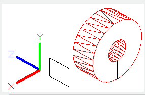
The revolving path and outlines could be as the following:
1. Open or closed
2. Planar or non-planar
3. Sol
id edge or surface edge 4. Single object (in order to stretch multiple lines, use the JOIN command to convert them to single object)
5. Single domain (in order to stretch multiple domains, use the REGION command to convert them to single object)
Users could use the DELOBJ system variable to delete outline automatically. If the association has been turned on, the effect of the DELOBJ system variable will be ignored, as well the original geometry graph will not be deleted.
The following objects could be revolving:
Curve, elliptic arc, 2D solid, 2D and 3D spline, wide line, arc, 2D and 3D polyline, ellipse, circle and domain.
Note: select planes and edge sub objects at the same time by pressing CTRL.
Users could not revolve objects nested in block or self-intersection. When revolving, it may ignore the width of polyline and rotate around the center of polyline path; the revolving direction is determined by right-hand rule.
Function Description:
Objects to rotate:
Specify objects to rotate around an axis.
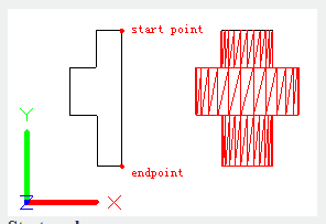
Axis start point:
Specify the start point of rotation axis. The positive direction of axis is from the first point to the second point.
Axis end point:
Specify the endpoint of rotation axis.
Start angle:
Specify angle offset for selected objects, the plane of objects is the beginning of rotation angle.
Angle of revolution:
Specify the rotation angle for selected objects.
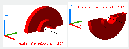
Inputting a positive angle, the selected objects will revolve along anticlockwise direction; on the contrary, inputting a negative angle, they will revolve along clockwise direction. Users could also drag cross cursor to specify and preview rotation angle.
Object:
Specify rotation axis by selecting object. The positive direction of axis is from the nearest point to the furthest point.
Users cold specify rotation axis by selecting straight lines, linear polylines and edges of solids or surfaces.
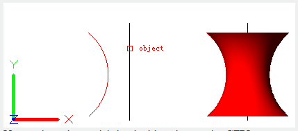
Note: select edges and their sub objects by pressing CTRL.
X : Specify the positive direction of X axis in current UCS to be the positive direction of rotation axis.
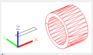
Y: Specify the positive direction of Y axis in current UCS to be the positive direction of rotation axis.
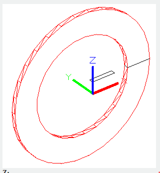
Z : Specify the positive direction of Z axis in current UCS to be the positive direction of rotation axis.
Article ID: 2333
Created: August 20, 2021
Last Updated: August 20, 2021
Author: GstarCAD MY /KW
Online URL: https://www.kb2.gstarcad.com.my/article.php?id=2333