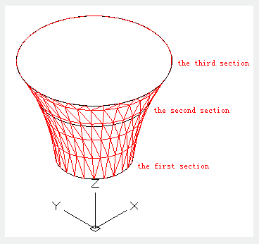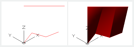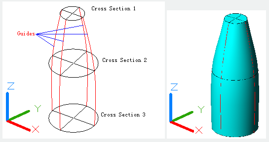
The LOFT command is used to create 3D solids or surfaces by several cross sections.
Command Access:
Ribbon : 3D > Modeling > Extrude > Loft
Menu : Draw> Modeling > Loft
Command : LOFT
Command Prompts:
Select cross sections in lofting order: Enter an option [Guides/Path/Cross sections only] :
Function Description:
Those cross sections determine the shape of 3D solid or surface and there must be at least two sections.

Lofting profile could be open or closed, planar or non-planar, and could also be edge of sub objects.

User could apply the LOFT command on the following objects or sub objects:
1.The following objects could be selected as cross sections: 2Dpolyline, spline, arc, elliptical arc, and line.
2.The following objects could be selected as path: 3Dpolyline, spline and line.
3.The following objects could be selected as guides: Spline and line. Users could set the DELOBJ system variable to delete cross sections, guides and path automatically.
Relative Glossary:
Select cross sections in lofting order:
Specify open or close cross sections in lofting order.
Guides:
Specify loft guides to control solid or surface shape. Users could specify control points to match corresponding cross sections.
Note:
The guide surface must intersect with each cross section. The guide surface starts from the first cross section. The guide surface ends at the last cross section. Users could select a few guides for lofting surfaces or solids and press ENTER to finish

Path: Specify loft path for solid or surface. The path must intersect with planes of cross sections.

Cross sections only: Create loft by cross sections without guides or path.
Article ID: 2208
Created: August 17, 2021
Last Updated: August 17, 2021
Author: GstarCAD MY /KW
Online URL: https://www.kb2.gstarcad.com.my/article.php?id=2208