The LEADER command is used to create a line to connect annotation and a feature.
Command Access:
Command : LEADER
Command Prompts:
Specify leader start point:
Specify next point:
Specify next point, or [Annotation(A)/Format(F)/Undo(U)] <Annotation>:
Relative Glossary:
Specify leader start point:
Draw a leader line to a specified point and prompt for the next point and options.
Annotation:
Insert annotation at the endpoint of the leader line.
The annotation could be a single line text or multiple lines texts and contain tolerance properties control box and blocks.
Pressing ENTER under the "Annotation" prompt before entering text, the following options will display:
Tolerance:
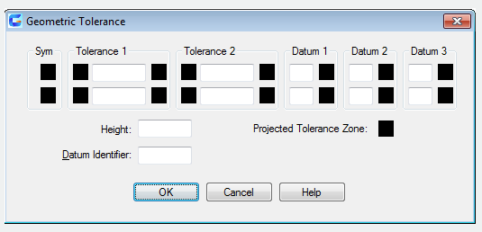
Users could use the "Geometric Tolerance" dialog box to create properties control box for geometric tolerance. In the properties control box, users could create Datum Identifier and Datum annotation. The LEADER command will be stopped after specifying the geometric tolerance.


Copy:
Copy text, a multiple text, and geometric tolerance of the properties control box or block and connect copies to the end point of leaders. Moving objects, the endpoint of leaders will be moved together.The current space of text (reference the DIMSTYLE or DIMGAP system variables) determines the insertion position of text and multiple texts. Any properties control box or block with geometric tolerance will be attached to the end point of leaders.

Block:
Insert a block to the end of leaders. The prompt is the same as the INSERT command. The block reference will be inserted to a certain position offsetting end of leader and connect with the leader. As the block moving, the end of leader will move together.
None:
End the command without inserting any annotations to the leader.
Mtext:
Specify the insertion point of multiple texts and use the "Text Formatting" to create multiple texts.
Insert characters. Users could insert prefixes and suffixes of characters string into angle bracket (<>) and unit conversion into square bracket ([]). The unit settings and current text style determine the display of text. Multiple texts will be aligned by vertical center and horizontal in the X axis direction of the last two endpoints of leader. Multiple texts could offset a distance from base line; it is specified in "Text" option of New, Modify and Override of Dimension Style Manager Dialog box. If specifying a negative offset distance, multiple texts will be regard as basic dimension

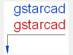
Format: This option is used to control the leader pattern and including arrows or not.
Spline:
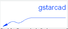
Create a leader line by a spline. The vertex of leader line is control point and the weight of control point is 1.
Straight: Create a leader line by a group of straight lines.
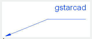
Arrow: Create arrows at the beginning of leader lines.
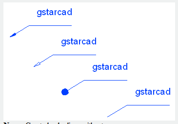
None : Create leader lines without arrows.
Undo:
Quit the last vertex of leader line and display the previous prompt.
Article ID: 2196
Created: August 17, 2021
Last Updated: August 17, 2021
Author: GstarCAD MY /KW
Online URL: https://www.kb2.gstarcad.com.my/article.php?id=2196