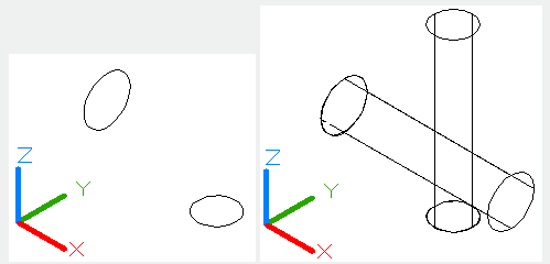
The EXTRUDE command is used to create 3D solid or surface by extruding the dimension of selected object.
Command Access:
Ribbon : 3D > Modeling > Extrude >Extrude
Menu : Draw > Modeling > Extrude
Command : EXTRUDE
Command Prompts:
Current wireframe density: ISOLINES=4
Select objects to extrude:
Specify height of extrusion or [Direction/Path/Taper angle]:
If delete defining objects? [Yes/No]:
Function Description:
Users could create 3D surface or solid by extruding open objects or closed objects.
The DELOBJ system variable will remind users to delete object and path when creating solids or surfaces. Object Selection: Specify the objects to extrude. Users could extrude the following objects and sub-objects:
Lines
Arcs
Elliptical arcs
2D polylines
2D spline
Circles
Ellipses
2D solids
Regions
surfaces
Relative Glossary:
Objects to extrude : Select objects to extrude.
Height of extrusion:
Entering a positive value, the object will be extruded along the Z axis positive direction; entering a negative value, the object will be extruded along the Z axis negative direction.
By default, the object is extruded along the normal direction. It is no need to specify all objects in the same plane

Direction:
Specify the height and direction by two points.
Specify start point of direction:
Specify the first point in the direction vector.
Specify end point of direction:
Specify the second point in the direction vector.
Path:
Specify the path of extrusion for selected objects. The object profile will be extruded along the path to form a solid or curve.
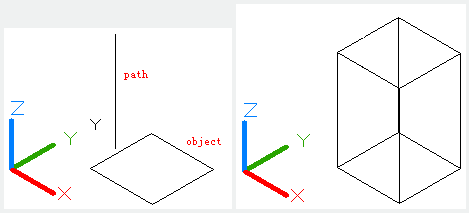
The selected object and path should on different plane without high curvature.
The extrusion begins with the selected object plane and keeps the direction along the path.
If there is no tangency segment in path, it will extrude selected object separately and equally divide connector along the path.
If the path is close, the selected object will be located on inclined plane. The starting section matches with the end section. If the selected object is not on inclined plane, it will be rotated.
Taper angle:
Specify the taper angle of extrusion.
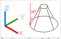
Inputting a positive angle, the selected object will be tapering to extrude.
Inputting a negative angle, the selected object will be extruded gradually larger.
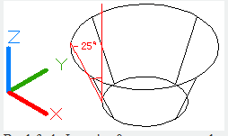
By default, Inputting 0 means to extrude selected object along vertical direction.
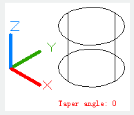
If users specify a larger angle or a larger height for extrusion, it may lead the object to converge at a point before reaching the height. The ring of region will be extruded to the same height
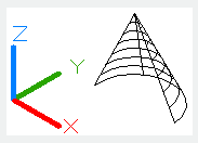
Angle of taper:
Specify an angle ranges from -90°to 90°.
Users could drag cursor to specify and preview taper angle. They could also drag cursor to preview extrusion height.
Above video sources from TUTORIAL - GETTING STARTED WITH GSTARCAD, enrol now for free.
Above video sources from TUTORIAL - GETTING STARTED WITH GSTARCAD, enrol now for free.
Article ID: 2124
Created: August 13, 2021
Last Updated: April 15, 2022
Author: GstarCAD MY /KW
Online URL: https://www.kb2.gstarcad.com.my/article.php?id=2124