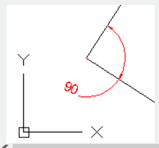
The DIMANGULAR command is used to create angular dimensions.
Command Access:
Ribbon : Annotation >Dimension > Angle
Menu : Dimension > Angle
Command : DIMANGULAR
Command Prompts:
Select arc, circle, line or <specify vertex>:
Specify dimension arc line location or [Mtext/Text/Angle/Quadrant]:
Function Description:
Users could measure angles by selected arcs, circles, straight lines, or 3 points.
Relative Glossary:
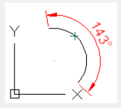
Select arc: Select one point on the arc to define dimensioning line. The center point of arc is the vertex of angular dimension and endpoints of arc become dimension extension line origins. It will create an arc dimension line between dimension extension lines.

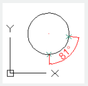
Select circle : Select one point to be the first dimension line origin and select another point to be the second dimension line origin. The second point does not need to be on the circle. The center point of circle is the vertex of angular dimension.
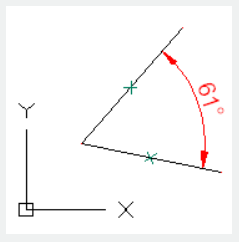
Select line : Select two lines to define an angle. It will define angular vectors by selecting each line. The intersection point of lines determines vertex of angle. The dimension lines go across angle of two lines. If the dimension line is not intersected with selected line, it will extend one or both selected lines to form dimension lines. The angle of arc is always smaller than 180.
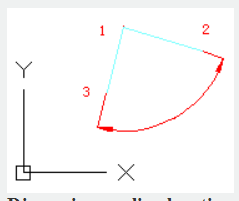
Specify Vertex : Specify three vertexes to define an angular dimension.
The endpoint of angle could be dimension line origin. It will create an arc dimension line between dimension extension lines. The dimension line is created from the angle endpoint to the intersection of dimension lines.
Dimension arc line location:
Specify location and direction of dimension arc.
Mtext:
Display the In place Text Editor. Users could edit annotation text by this option. Users could add something to value by adding a prefix before angle bracket or adding a suffix after angle bracket; they could also input special characters or symbols by control code or Unicode character strings. The current dimension style determines appearance of generated measured value.
Text:
Customized the annotate text under command prompt. The generated measured value will be displayed in angle bracket (<>).
User could reset the dimension style in "Text" option of New, Modify, and Override in Dimension Style Manager Dialog box.
Angle:
Modify the angle of the annotation text.
Quadrant:
Specify the quadrant that the dimension lies in. In the "Quadrant" state, if the annotation texts are placed beyond angular dimension, the dimension line will be extended past dimension extension line
Above video sources from TUTORIAL - GETTING STARTED WITH GSTARCAD, enrol now for free.
Article ID: 2074
Created: August 11, 2021
Last Updated: April 15, 2022
Author: GstarCAD MY /KW
Online URL: https://www.kb2.gstarcad.com.my/article.php?id=2074