Have you tried to annotate your isometric drawings? How about dimensions and text, is it appear properly? No it‟s not. The drawing looks isometric, but not the annotations. So how can you create isometric annotations?
Isometric Text
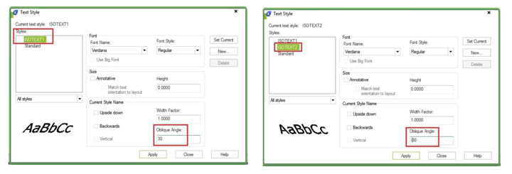
First, create two text styles within the Text Style dialog box. Use oblique angle 30 deg for one style and -30 deg for the other.

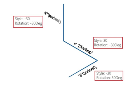
Now try to create text (single or multi line) with different styles and angle combination, then change the rotation to 30 deg or -30 deg. It depends on where you want to put it. See next image as reference.
Isometric Dimension
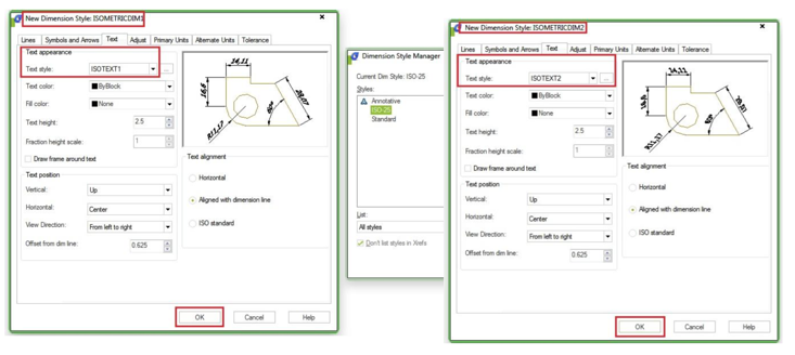
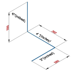
What about dimensions? You also have to create two styles within the Dimension Style Manager dialog box. One of the style use 30 deg text style, and the other one use -30deg.
Now place aligned dimension. Notice that the extension lines of the dimension placed are not perpendicular as the blue line. Now we have to do a little modification.
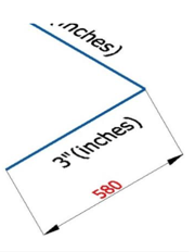
Activate DIMEDIT [enter], choose , then give 30 or -30 as oblique angle. Once again, depends where your dimension is.
Command: DIMEDIT
Enter type of dimension editing [Home/New/Rotate/Oblique] :
Select objects: 1 found
Select objects:
Enter obliquing angle (press ENTER for none):
-30
O
See this image as reference.
Article ID: 1098
Created: April 3, 2016
Last Updated: April 3, 2016
Author: kbadmin
Online URL: https://www.kb2.gstarcad.com.my/article.php?id=1098